
Diagram on how to wire 3PDT footswitch Guitar pedals, Diy guitar
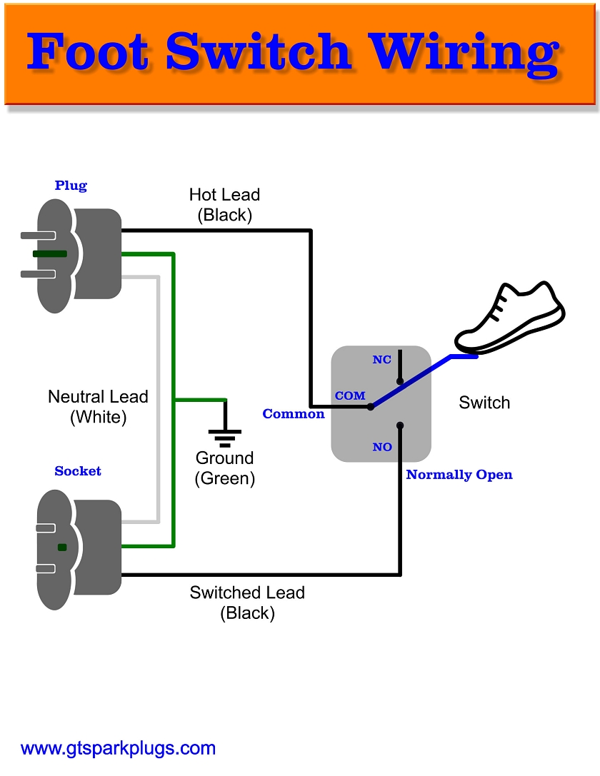
Foot Switch Wiring Diagram Above is a simple diagram that shows how things get wired. I used an old extension cord and cut a short piece for the socket side. The wiring colors in the USA are BLACK for HOT, WHITE for NEUTRAL and GREEN (or GREEN/YELLOW) for GROUND. As the wiring shows we are really only wiring the BLACK wires to the switch.

sewing machine foot pedal wiring diagram AnmarLeizxha
Foot Switch ConnectionIn This video, we are going to learn how to use pedal Switch in Electrical CircuitWhat is a pedal switch?A Foot Pedal Switch is a switc.

Sonomed A2500 Foot Switch Wiring Diagram
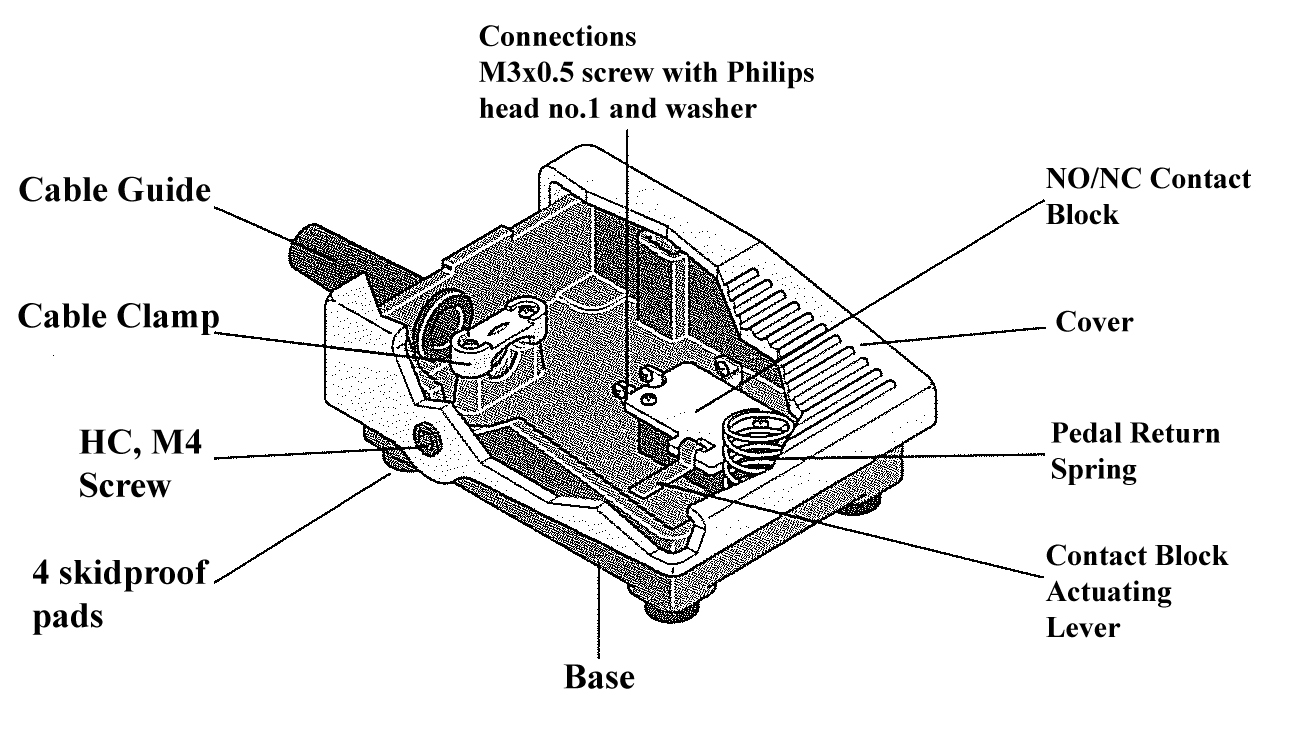
wire from switch down thru hole. Place switch housing flat down on casting deck and using housing as drill template, mount switch to deck using either #10 pen head screws or 3/16" dia. pop rivets (not furnished). STEP 3: Hook up wire per diagram. NOTE: All electrical connections should be protected with tape or rubber covering to
switch leg wiring
1. Executive foot operated switches are furnished with a non-skid base pad and can be mounted with the base pad attached. 2. Use two number 6 machine screws and two number six lock washers when mounting foot switch to full guard. (See Diagram "C") DIAGRAM "B" #522-B14 Full Guard with assembly hardware and instructions available upon.

Foot Switch Wiring Diagram Wiring Diagram
LINEMASTER Switch Corporation Tel (860) 974-1000 29 Plaine Hill Rd, P.O. Box 238 Woodstock, Connecticut 06281-0238 USA Fax (800) 974-FOOT(3668) LIT-034 Rev. D The Hercules foot switch has been Linemaster's signature switch since the beginning. It gets its name from being the most rugged and tough foot switch on the market. The Hercules was

Sonomed A2500 Foot Switch Wiring Diagram
7. The circuit designations shown in Diagram "C" are at assembly. For 974-S only, the left side interior switch is reverse actuated in the foot switch housing. For example, the normally closed terminal (NC) marking molded into the switch body will provide a normally open circuit when the interior switch is assembled in the foot switch housing. 8.
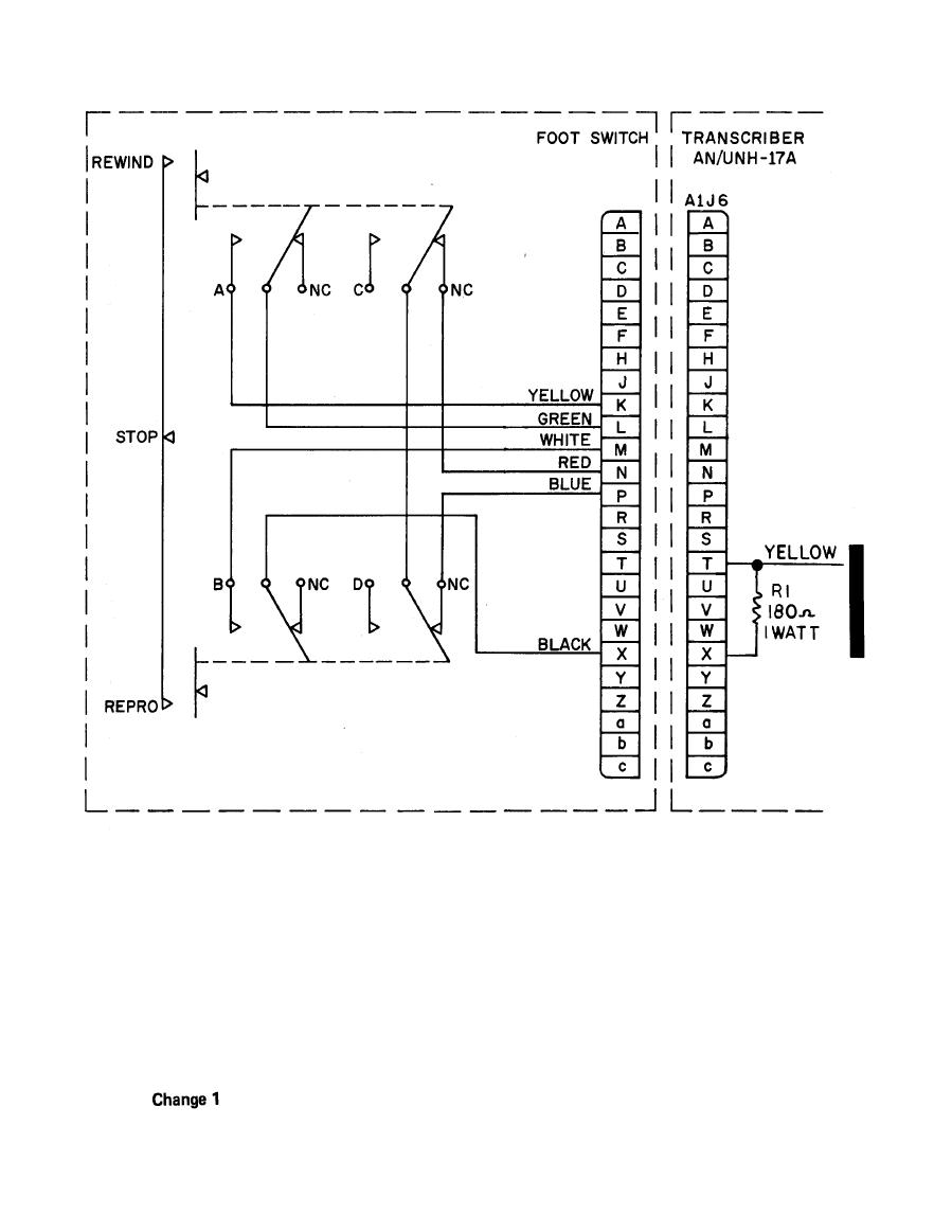
Figure 611. FOOT SWITCH WIRING DIAGRAM
The G-Series foot switches can include from one to three switches, and up to four independent SPDT circuits. They do not come with cables. The user installs the appropriate cable and strain relief to the switch. G500 models have one switch, G502 models have two switches, G503 models have three switches, and G504 models have four circuits.

13 Best Clipper Foot Switch Wiring Diagram
1. Clipper foot operated switches are furnished with two 7/32 IN. (5.6 mmØ) diameter mounting holes on 2-7/8 IN. (73 mm) centers. 2. Use two number 10 machine screws and two number 10 lock nuts when mounting foot switch to full guard. (See Diagram "C") Form 522-J32 Rev. A #10 Locknut Clipper Foot Switch #522-B14 Full Guard with assembly.
Foot Switch Wiring Diagram Free Wiring Diagram
The foot switch wiring diagram using a contactor is shown below. This wiring diagram can be done by using a foot switch, a contactor, and MCB as per the shown diagram below. Foot Switch Wiring Diagram. In the above circuit, the power wiring is very simple. MCBs downside two terminals are given as neutral and phase whereas, from MCB's output.

Diagram Power Wheels Foot Switch Wiring
A foot switch wiring diagram is essential for anyone looking to set up a foot switch for their electrical devices. Whether you want to control lighting, audio equipment, or other appliances with your feet, a foot switch can provide convenience and hands-free operation. This article will guide you through the process of wiring a foot switch.

foot switch wiring diagram Sonomed a2500 foot switch wiring diagram
In each switch, lug 2 is common. Lugs 1 and 3 are the two states of the switch. In other words, in one state the foot-switch connects lug2 to lug1. In the other state it connects lug2 to lug3. And, it does this simultaneously for all three switches. fig.3. Fig.3 shows the two different "states" of the 3PDT foot-switch.

Sonomed A2500 Foot Switch Wiring Diagram
Have a look at the back of the foot switch and you will see 2 slots and the words 'Open'. With a screwdriver around 3mm wide insert it into the slot with the blade closest to the centre. Then twist a little whilst pulling the 2 parts apart. Do the same in the other slot. Here is a quick video on where to position the screwdriver and twist.

13 Best Clipper Foot Switch Wiring Diagram
Removing and reinstalling a Ridgid 300 forward/reverse switch.Showing close-up of switchbox wiring with explanations of foot switch connections with fwd/rev.
DIY Foot Switch GTSparkplugs
THE WHITE AND BLACK LEAD COLORS ON THE FOOT SWITCH CABLE HAVE NO RELEVANCE TO HOUSEHOLD WIRING. ELECTRICAL RATING (MODEL NUMBER IN PARENTHESIS): 10 AMPS @ 125/250 VAC (S100-1002, S400-1002, S420-1002) 15 AMPS @ 125/250 VAC (S100-1502, S400-1502, S420-1502) WARNING: TO AVOID PERSONAL INJURY, DO NOT USE FOOT SWITCHES ON MACHINERY LACKING.

Foot Switch Kit Up & Down AnchorLift Direct
G-Series heavy-duty foot switches (see below for wiring diagrams) can include from one to three switches, and up to four independent SPDT circuits. They do not come with cables. The user installs the appropriate cable and strain relief to the switch. G500 models have one switch, G502 models have two switches, and G503 models have three switches.

Sonomed A2500 Foot Switch Wiring Diagram
DIAGRAM "A". 5. Loosen or remove cord clamp screws; remove baseplate; insert cord and connect inner leads of cord to appropriate switch terminals. Check orientation of cord clamp for cord size range and re-tighten cord clamp screws alternately. (See Diagram "B") Use 0.250 to 0.340 Diameter, (6.4 to 8.6mmØ) cord with clamp in this.